
Lian Li Uni Fan SL120 V2 Shiyong-Shuomingshu
PDF 手册 · 2 Pages
中文



快速检查
答案不正确,请重试。
使用 AI 与您的 Lian Li Uni Fan SL120 V2 手册聊天
从您的 Lian Li Uni Fan SL120 V2 手册中获取即时 AI 答案
询问有关 Lian Li Uni Fan SL120 V2 的任何问题。答案来自本手册及其所依据的页面。
提问 问题
您会推荐 Uni Fan SL120 V2 吗?
是 否常见问题 问题
您必须专门连接到 PWM 风扇接口和 5 V ARGB 3 针接口。使用任何其它电压类型都可能导致损坏。
此回答有帮助吗?
不可以,切勿连接到 12 V 接口。这样做可能导致灯效系统或电源模块永久损坏。
此回答有帮助吗?
使用随附的 M5x10 螺丝,不要使用垫圈。其他螺丝可能无法妥善固定风扇。
此回答有帮助吗?
厚度为 28 毫米。它使用沉头螺丝孔以兼容标准长螺丝。
此回答有帮助吗?
可以,但互锁卡扣可能会干扰端口。幸运的是,此特定卡扣可拆卸以解决间隔冲突。
此回答有帮助吗?
可用型号包括 SL120 和 SL140 尺寸,有黑色或白色选项,例如 UF-SL120V2-1B。
此回答有帮助吗?
是的,包装中包含风扇连接线缆,以允许高效地级联设备。
此回答有帮助吗?
優勢 和 劣勢
优势

- 方向性连接器设计可防止电源电缆连接错误。
- 拉拔连接器机制有效抵抗振动导致的松动。
- 可拆卸的互锁卡扣允许在特定散热器布局上安装。
- 沉头螺丝孔无需垫圈即可轻松适配标准长螺丝。
- 包含特定 M5x10 螺丝以确保安装稳固。
缺点

- 若误连接到 12 V 接口,存在永久损坏风险。
- 需要特定的 M5x10 螺丝,因为其他螺丝可能无法正确固定。
- 28 毫米厚度有时可能会干扰较小的机箱配置。
- 说明文件要求双语理解以确保安装完全清晰。
- 可拆卸卡扣在散热器安装过程中增加了额外步骤。
产品 规格
风扇连接器
4 针 PWM + 3 针 ARGB (+5V/数据/GND), 可拆卸线缆
尺寸
11.99x11.99x2.79 厘米 (宽 x 高 x 深), 11.99 厘米风扇
风扇转速
250-2000 转/分
风扇轴承
流体动态轴承 (FDB)
电压范围
5-12V
功耗
2.04W
灯光
RGB
制造商保修
2 年
产品 描述
Upgrading Your Cooling Setup
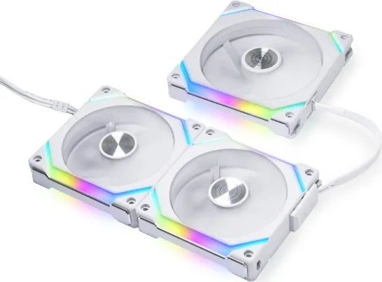
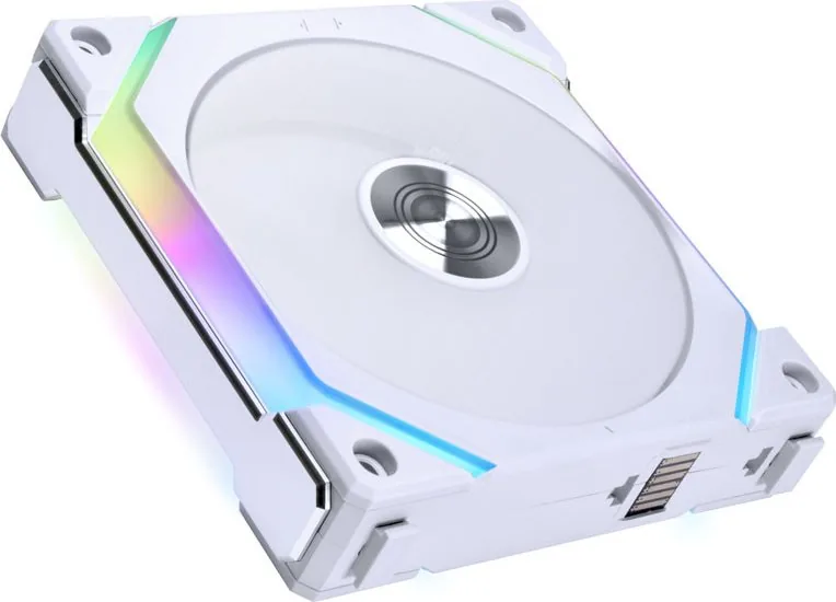
The Lian Li Uni Fan SL120V2 RGB Manual provides essential insights into modern chassis cooling solutions. Installing these fans requires precision significantly for safety and performance. Power cable installation requires attention to directional modular sockets. You must connect male-female plugs while ensuring pins remain covered by the plate. This design prevents accidental disconnection during operation. The pulling connector mechanism features a specific latch system designed to resist loosening from vibrations common in high-performance builds. Each package typically contains one PC unit of the fan along with four screws for secure attachment during assembly.
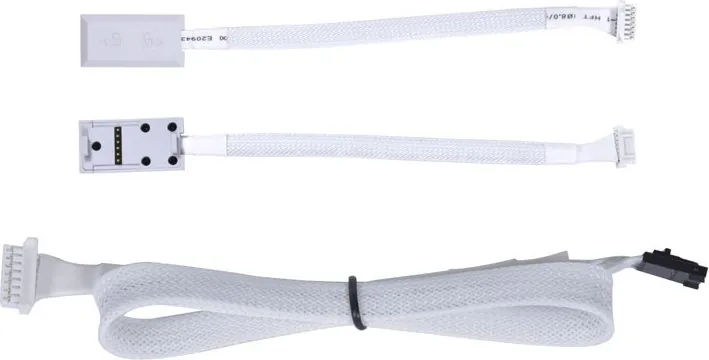
Note that connecting the power module to the motherboard involves critical steps regarding voltage specifications. You must connect to the PWM fan header and the 5 V ARGB 3 pin header specifically. Never connect to a 12 V connector. Doing so can cause permanent damage to the lighting system or power module. Safety protocols are emphasized to protect your expensive components. Fan to fan connection cables are included within the packaging to daisy chain devices efficiently for synchronized lighting effects. This ensures a seamless visual experience across your entire system layout.
The fan thickness measures 28 mm, utilizing counterbore screw holes for compatibility with standard long screws. However, using gaskets along with long screws is discouraged because it compromises the intended fit. Only use the included M5x10 screws provided in the box to ensure fans remain secure. This is crucial for maintaining structural integrity within your case. When mounting fans on radiators, the interlocking key might interfere with inlet or outlet ports. Fortunately, this specific key is removable to resolve spacing conflicts without compromising the frame stability.
Available variants include UF-SL120V2-1B and UF-SL120V2-1W for twelve centimeter frames. Larger fourteen centimeter options exist as UF-SL140V2-1B or UF-SL140V2-1W. Understanding these specifications ensures optimal airflow and thermal management for your specific hardware needs. Proper assembly guarantees longevity and prevents hardware failure due to improper electrical connections. Enthusiasts should review these specifications before beginning any build process to avoid costly mistakes and ensure maximum performance from your cooling rig. Notes on maintenance suggest keeping dust away from the blades. Cleaning should be gentle to prevent bearing damage over time. Users often appreciate the anti-vibration pads included to reduce noise levels. It is recommended to double check all wiring diagrams before powering on the system to prevent any unexpected issues during initial startup. Following the provided guidelines helps maintain warranty coverage and ensures the product functions as designed by the manufacturer for years to come.
搜索:67,706 在线手册


输入品牌或型号