Copyright
©
ICY DOCK International. All Rights Reserved. 650266 VER 1.0
ToughArmor
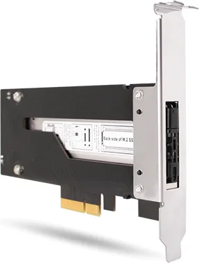
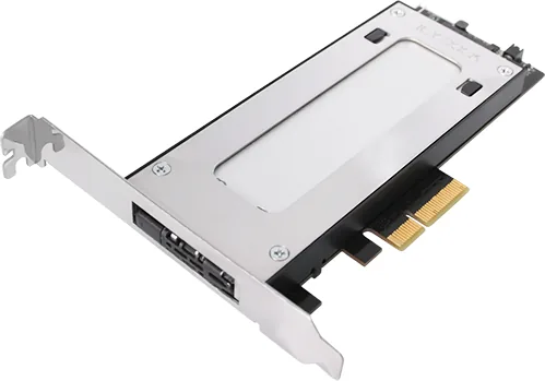
M.2 NVMe SSD to PCIe 3.0 x4 Hot-Plug Mobile Rack for PCIe Expansion Slots
User manual
Device
1 x #6-32*5 hexagon
Phillips screw with washer for device
Note: P lease u t he inc luded sc rews to s e ure t he dev
Front View
1
2
Drive t ray eject ion button
Half Height
IO Faceplate
Full Height
IO Faceplate
LED indicator (Power: solid green LED; Drive access: flashing green LED)
1
2
Full / Half height expansion slot faceplate
(Default)
Drive T
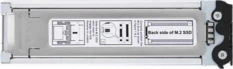
Adjustable M.2 SSD Locker
Golden Finger Position
Top View
3
操作步骤
操作步驟製品
I Iions G Guía
de
2 Pin Header for Front Panel LED
1
2
1
2
Full Height IO Faceplate
Half Height IO Faceplate
PCIe 3.0 x4 Golden Finger (Compatible with PCIe x4 / 8 / 16 Slot )
3-1
3-2
3-3 3-4
Push the tray ejection button to eject
the drive tray
Pull to remove the drive tray T
down to the bottom side.
3
3
4
4
设备安装步骤
Deion Iio n
Iio n
裝置安裝步驟
デバ
dposi Ial aió n dpo s
4
3-5 3-6
3-7 3-8
2
3
Use the included #6-32*5 screw to secure the device.
Fully connect the device’s PCIe connector into the system’
(Optional) Connect the 2 Pin header to the system’s front panel LED
cable for LED activity indications.
1
2
3
1
3-9
3-10
1
2
Press down the top cover and push towards
the guided arrow to open the top cover
With the M.2 SSD laying flat on the tray
the adjustable locker to secure the M.2 SSD.
Remove the protective film from the thermal
pad located inside the drive tray
1
2
T
SSD, align the gap on the connector of the M.2
SSD to the drive tray’s rear metal pin. Then
insert the M.2 SSD towards the pin, exposing
the SSD’s golden finger connector
Latch the rear end of the top cover into the rear
tray’s groove first, then press down the front end
of the top cover to complete M.2 installation.
NOTA
注釋
5.
3. Due to different drive specifications for the device activity signal, some drives may not support
the access LED. If the LED does not function, but the user can read and write to the drive, it
falls under this category. If the LED does not function, and the drive cannot be read or written
to, please contact us for troubleshooting.
2
1.
5.
3. Auf Grund unterschiedlicher Spezifikationen kann es vorkommen, dass manche Laufwerke das
Aktivitätssignal nicht unterstützen. Dieser Fall trifft zu, wenn Sie Lese- und Schreibzugriff auf das
Laufwerk haben, die LED aber kein Zugriffssignal anzeigt. Sollten Sie keinen Lese- und
Schreibzugriff auf das Laufwerk haben und die LED auch nicht funktionieren, so kontaktieren
Sie uns bitte zur zur Fehlerbehebung.
1. ICY DOCK
2. I
2. ICY DOCK ne pourra être tenu responsable de la perte ou dégradation de tout logiciels, matériels
ou données suite à des dommages ou des disfonctionnements de matériels utilisés avec nos
produits ICY DOCK. La responsabilité de ICY DOCK ne pourra être engagées que pour ces
propres produits.
1. ICY DOCK
3. A cause des différentes spécifications des signaux d'activité, certains disques durs ne supportent
pas l'accès. Si la LED témoin ne s’allume pas, alors le disque dur n’est pas pris en charge,
contactez-nous pour un dépannage.
5. Si vous souhaitez obtenir plus d’informations sur nos produits, vennez visiter notre site:
http://www.icydock.fr
4. To utilize the
Hot-Plug
function, the host must also support
Hot-Plug
. To check if your host
supports
Hot-Plug
, please refer to the motherboard or controller card specifications and user
manual.
4. Zur Nutzung der Hot-Plug-Funktion muss der Host auch Hot-Plug unterstützen. Prüfen Sie anhand
der Spezifikationen und Bedienungsanleitung von Motherboard und Controller-Karte, ob Ihr Host
Hot-Plug unterstützt.
4. Pour profiter pleinement la fonction
Hot-Plug
, vérifiez que votre configuration accepte
la fonction
Hot-Plug
.
3.
5.如欲知更多产品资讯,欢迎上网浏览本公司网站:http://www.icydock.com 。
1.本公司保留产品升级与变更之权利,如改版,恕不另行通知。
2.本公司仅负责ICY DOCK 产品本身相关的维修。任何跟其它软件、硬件、数据相关的故障请联络其相
关公司协助维修。
5.如欲知更多產品資訊,歡迎上網瀏覽本公司網站:http://www.icydock.com 。
2.本公司僅負責ICY DOCK 產品本身相關的維修。任何跟其它軟體、硬體、資料相關的故障請聯絡其相
關公司協助維修。
1.本公司保留產品升級與變更之權利,如改版,恕不另行通知。
5. Si tiene alguna pregunta o duda acerca de los productos ICY DOCK, visite nos en el sitio web
http://www.icydock.com
3. Debido a las diferentes especificaciones de las unidades para la señal de actividad a dichas unidades,
algunas de estas puede que no admitan el LED de acceso. Si el LED no funciona pero el usuario
puede realizar operaciones de lectura y escritura en la unidad, dicho LED se encuentra dentro de
esta categoría. Si el LED no funciona y no se pueden realizar operaciones de lectura o escritura
en la unidad, póngase en contacto con nosotros para solucionar el problema.
1. ICY DOCK se reserva el derecho de cambiar las especificaciones técnicas no relacionadas y está
sujeto a cambio sin previo aviso.
2. ICY DOCK no asumirá ninguna responsabilidad por ningún software, hardware o dato almacenado
en los productos ICY DOCK, o que interactúe con estos, que provoque daños o averías. ICY DOCK
solamente asumirá la responsabilidad de reparaciones y tareas de servicio de productos ICY DOCK.
5. ICY DOCK製品に関するお問い合わせは弊社のホームページhttp:// www.icydock.comへアクセスしてください。
2. 当公司はただICY DOCK製品自身と関連している修理だけ責任を負います。いかなるとの他のソフ卜ウェア、
データと関連している故障はその関連している会社と連絡し、修理を協力して下さい。
1. 当公司は
因为硬盘LED 外送讯号的规格根据不同硬盘厂商会有所不同,产品的LED 指示灯灯号。
如果数据读写没有问题,则不影响操作,如果LED指示灯不亮亦无法读写数据,请联络我们。
因為硬碟LED 外送訊號的規格根據 ,有一些硬碟不 支持產品的LED 指示燈燈
號如果數據讀寫沒有問題,則不影響操作,如果LED 指示燈不亮亦無法讀寫數據,請聯絡我們。
3.
HDD出力信号仕様はメーカーにより異なります。場合によって一部分HDDが本製品のLEDランプに対応できない
場合があります。も
書きできない場合、問い合わせください。
3.
4.
若欲完全使用Hot-Plug
的功
能,主机板端对应接口本身需具备Hot-Plug 功能。
4.若欲完全使用Hot-Plug 的功能,主機板端對應接口本身須具備Hot-Plug 功能。
4.
フルでHot-Plug機能を使用する場合、Host側もHot-Plug機能に対応する必要があります。
4. Para utilizar la función de conexión en caliente, el dispositivo principal también debe admitir esta
función. Para comprobar sea el dispositivo principal admite la función de conexión en caliente,
consulte las especificaciones y el manual del usuario de la placa base o de la tarjeta controladora.